Assembling Guide
Tip
It is recommended to follow the order of the steps below.
1 ESC Upgrade
The RC car comes with a receiver integrated ESC, which is not ideal for hacking the drivetrain (Thank to DonkeyCar's FAQ). Therefore, we need to put a microcontroller-friendly ESC on the board.
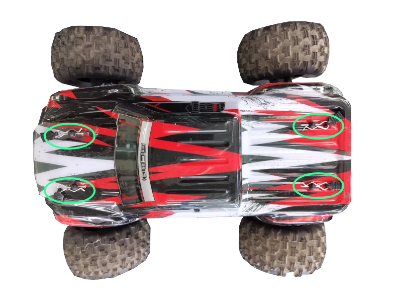
1.1 Remove Stock Cover
Expose the components under the hood by removing the clips as shown below.
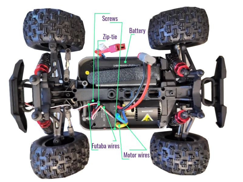
1.2 Remove Stock ESC
- Disconnect and remove the battery.
- Unplug the (blue and yellow) motor power wires (on the ESC) .
- Unplug two sets of PWM signal wires with Futaba connectors on the ESC 3x3 pin connector.
- Cut the zip-tie on the signal wires.
- Remove two screws locking the stock ESC.
Tip
Servo motor is underneath the ESC.
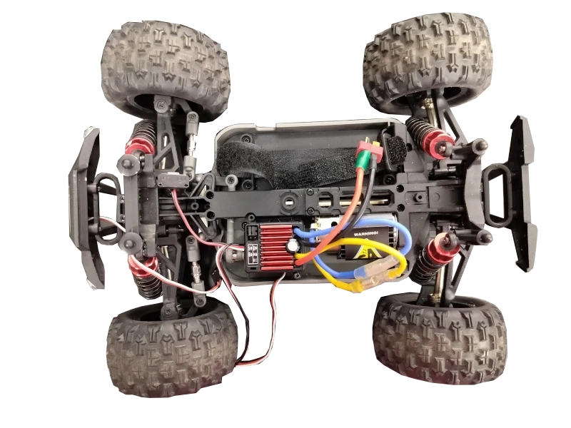
1.3 Replace (Quicrun 1060 Brushed) ESC
- Set the driving mode to F/R by removing the jumper cap on the top row of the 3x2 header pins.
- Notify the ESC that LiPO battery will be used by placing the jumper hat on the bottom row of the 3x2 header pins.
- Connect the motor wires (yellow and blue) to the new ESC (matching the color is recommended).
- Mount (tape) the new ESC on top of the servo motor.
Success
It is recommended to mount the new ESC as shown below.
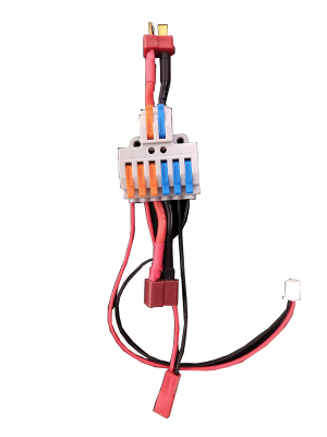
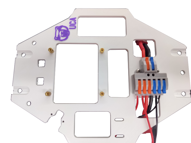
2 Assemble Power Distributor
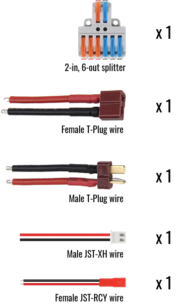
The power distributor is a 2-input, 6-output wire splitter. The wires in the same color are connected together (orange to orange, blue to blue).
2.1 Prepare
- 1x 2-in, 6-out wire splitter.
- 1x Male T-Plug wires (input).
- 1x Female T-Plug wires (output).
- 1x Male JST-XH wires (output).
- 1x Female JST-RCY wires (output).
- 2x M2.5x12mm screws
- 2x M2.5 nuts
Success
Peel extra skin off the wires. Or the levers may bite the skins instead of the exposed metal (broken circuit).
2.2 Assemble
Danger
Finger pinch hazard.
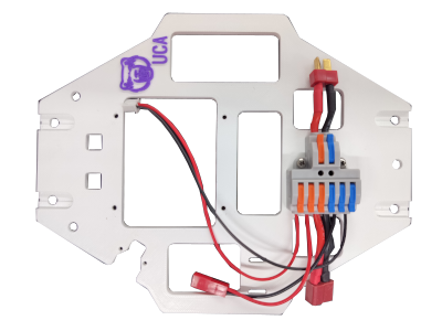
2.3 Attach to the bed
3 Stack Control Tower
3.1 Prepare
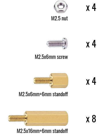
3.1.1 Fasteners
- 4x M2.5 nuts
- 4x M2.5x6mm screws
- 4x M2.5x6mm+6mm standoffs
- 8x M2.5x16mm+6mm standoffs
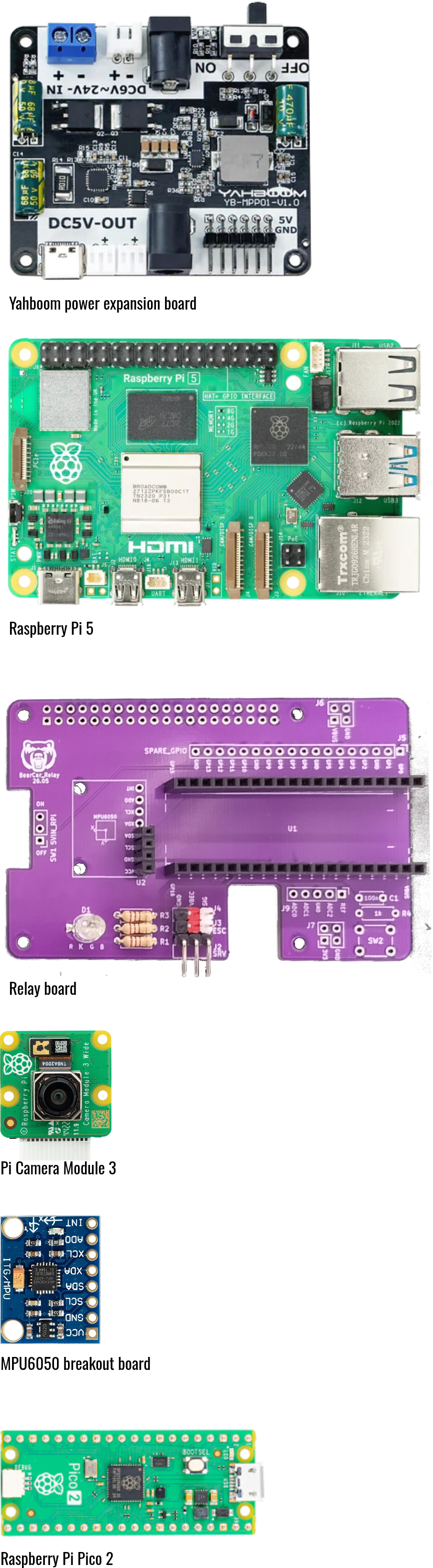
3.1.2 Electronics
- 1x Yahboom power expansion board
- 1x Raspberry Pi 5
- 1x BearCar relay board
- 1x Raspberry Pi Camera Module 3
- 1x Raspberry Pi Pico 2
- 1x GY-521 MPU6050 IMU breakout board
3.2 Set foundation
Note
Need 4x M2.5x6mm+6mm standoffs and 4x M2.5 nuts
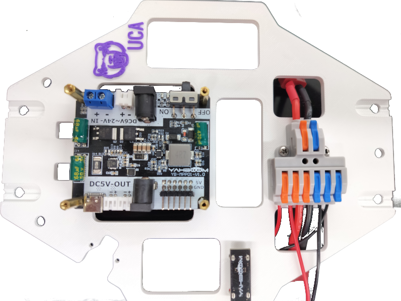
3.3 Stack power expansion board
Note
Need 1x Yahboom power expansion board and 4x M2.5x16mm+6mm standoffs.
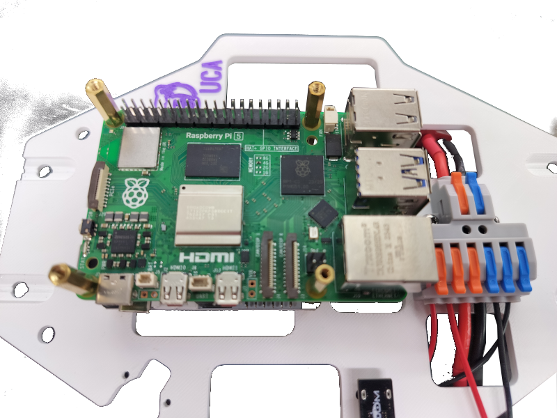
3.4 Stack Raspberry Pi
Note
Need 1x Raspberry Pi 5 and 4x M2.5x16mm+6mm standoffs.
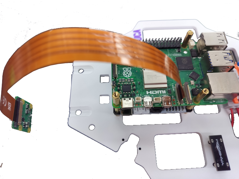
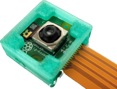
3.5 Insert Pi camera
Note
Need 1x Raspberry Pi Camera Module 3
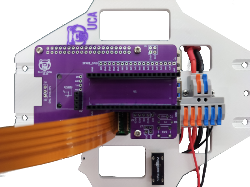
3.6 Stack relay board
Note
Need 1x BearCar relay board and 4x M2.5x16mm+6mm standoffs.
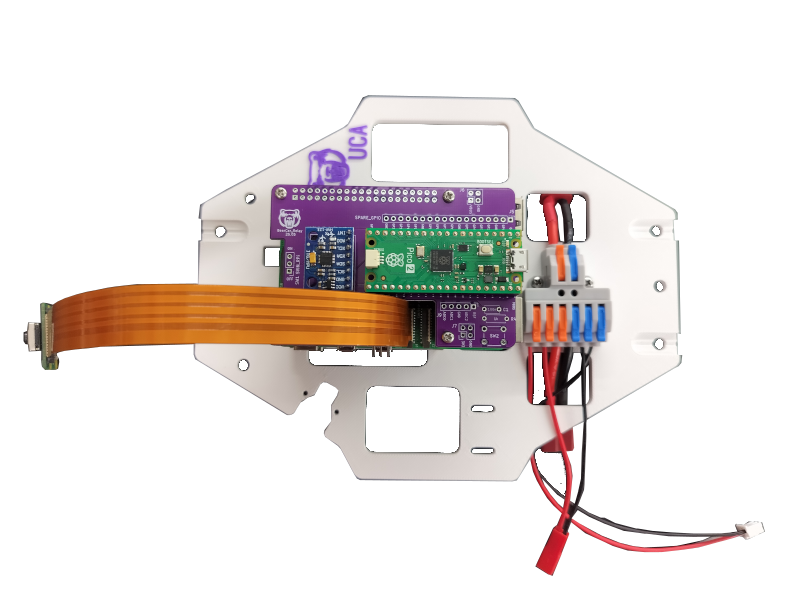
3.7 Stack Pico and IMU
Note
Need 1x Raspberry Pi Pico 2, 1x GY-521 MPU6050 breakout board and 4x M2.5x6mm screws.
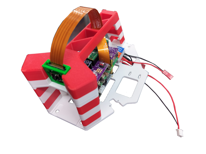
4 Assemble (Handled) Shield
4.1 Put camera in case
Warning
Careful with camera cable's facing.
4.2 Assemble handle
Note
Need 3x M4x16mm screws.
5 Car-Shield Integration
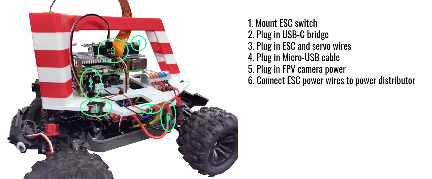
ESC and Servo Wiring
- White - SIG
- Red - VBEC
- Black - GND
BearCar Boot-Up
- Plug in a Raspberry Pi OS flashed micro-SD card to Raspberry Pi.
- Connect monitor, keyboard and mouse to Raspberry Pi.
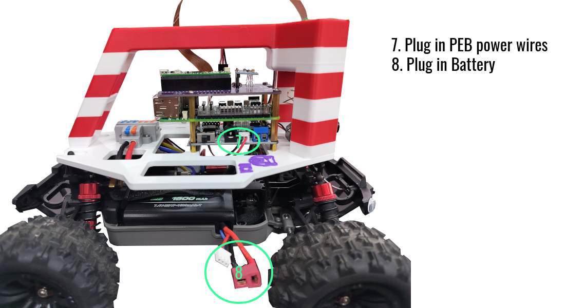
- Connect battery.
- Turn on the switch on the Power Expansion Board.
- Turn on the ESC switch.
System Shutdown
Whenever you are done with the BearCar, remember to: 1. Turn off the ESC. 2. Shutdown Raspberry Pi. 3. Turn off the PEB. 4. Disconnect the battery.